Equipment · Muninmax
FEC & FCM Pumps
MNM designs and manufactures FEC pumps for product-contact duties and FCM pumps for non-product-contact water and hot-water utility duties. Select the family for the service before selecting a motor configuration.
Discuss Your FEC & FCM Pumps Requirements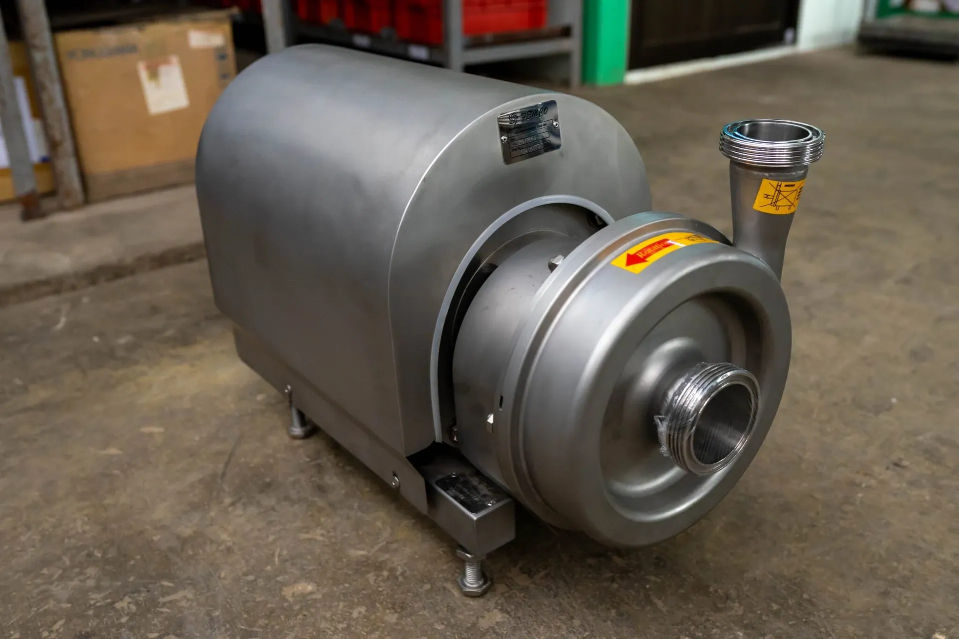
FEC Pumps
Designed for evaporation systems, product transfer and CIP circulation.
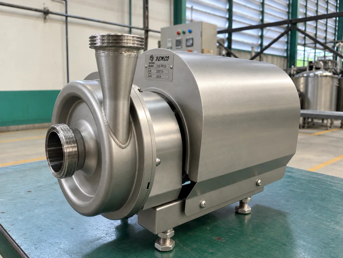
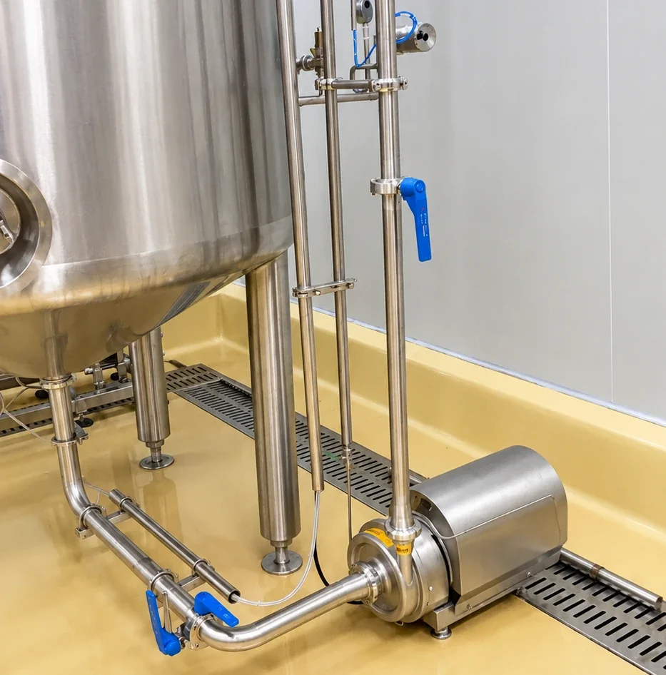
MNM designs and manufactures FEC pumps for product-contact applications. The FEC range is designed specifically for evaporation systems to handle the impact of liquid flowing down from an elevated evaporator into the pump. FEC pumps are also used for product transfer and cleaning-in-place (CIP) circulation.
Materials and Seals
Product-contact metal parts of FEC 5, FEC 10 and FEC 25 pumps, including the casing and impeller, are made of AISI 316L stainless steel.
Fluid-contact elastomer seals and O-rings use EPDM as standard. Alternative materials can be selected to suit project requirements.
Models and Motor Options
| Model | Available motor power options |
|---|---|
| FEC 5 | 0.55 kW; 0.75 kW |
| FEC 10 | 0.75 kW; 1.1 kW; 1.5 kW; 2.2 kW; 3 kW; 4 kW |
| FEC 25 | 5.5 kW; 7.5 kW; 11 kW; 15 kW |
Motor power is one part of pump selection. Flow rate, head and the operating conditions determine the configuration for the application.
FEC 5
FEC 5 is available with 0.55 kW and 0.75 kW motors. The listed dimensions are the same for these two configurations. The listed weight of 41.5 kg applies to the 0.75 kW configuration.
FEC 10
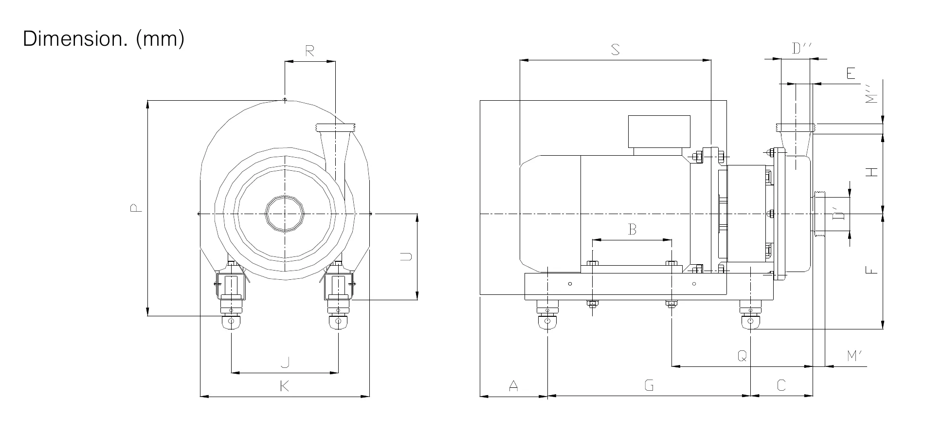
FEC 10 offers motor options from 0.75 kW to 4 kW. Use the dimensions for the selected motor configuration together with the FEC 10 drawing. The 0.75 kW and 1.1 kW configurations share the listed dimensions of the 1.5 kW configuration.
The reference performance curves describe the specified reference configuration; matching dimensions do not establish identical pump performance.
FEC 25
FEC 25 offers 5.5 kW, 7.5 kW, 11 kW and 15 kW motor configurations. Dimensions are listed by motor option, and reference curves are provided with their operating conditions.
Dimensions and Reference Curves
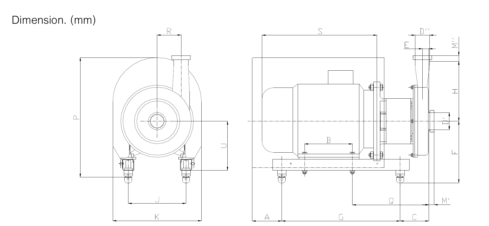
Read each dimension table alongside the drawing for that model. Dimensions are in millimetres and retain the drawing's lettered reference positions. Use the performance curves with the stated motor, speed, impeller and frequency conditions when discussing the required duty.
Discuss Your FEC Pump Application
Share the product or CIP duty, required flow rate and head or pressure, operating temperature, installation arrangement and connection requirements. For evaporation service, describe how liquid enters the pump from the evaporator.
Request FEC Pump Information
FCM Pumps
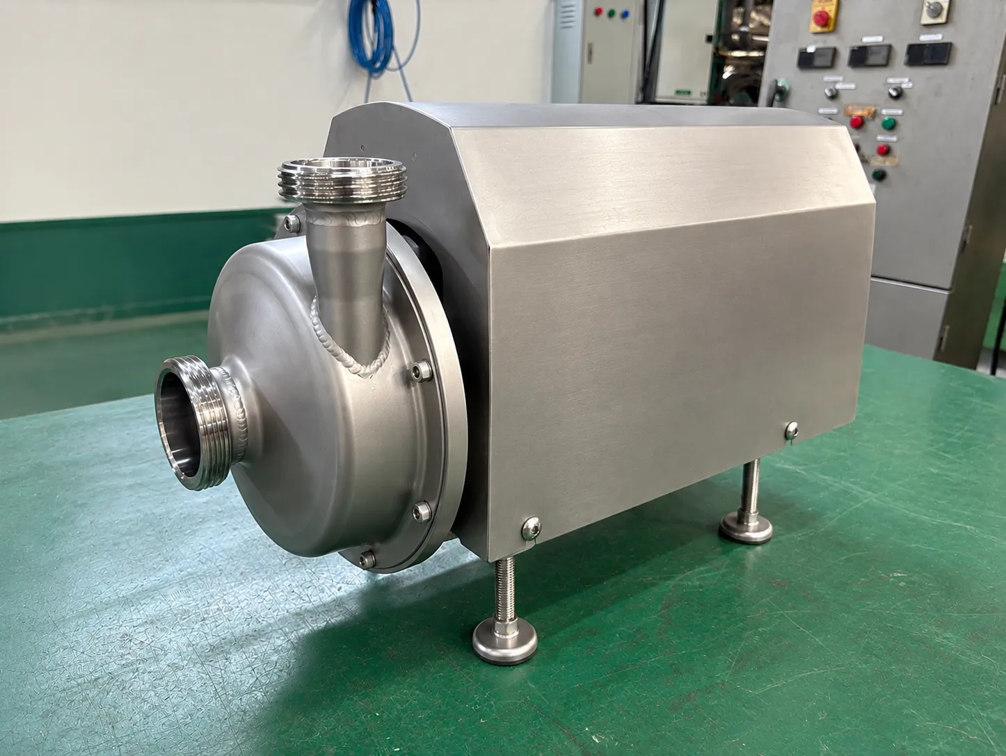
Utility pumping for water and hot water.
MNM designs and manufactures FCM pumps for non-product-contact utility applications, including water and hot water. The pump configuration is selected to suit the utility system and required operating duty.
Materials and Seals
The pump casing and impeller are made of AISI 304 stainless steel across the FCM range.
Water-contact elastomer seals and O-rings use EPDM as standard. Alternative materials can be selected to suit project requirements.
Motor Power Options
| Pump range | Available motor power options |
|---|---|
| FCM | 0.75 kW; 1.1 kW; 1.5 kW; 2.2 kW; 3 kW; 4 kW |
Select the motor and pump configuration against the required flow, head and operating conditions. Motor power alone does not specify pump capacity.
Dimensions and Weights
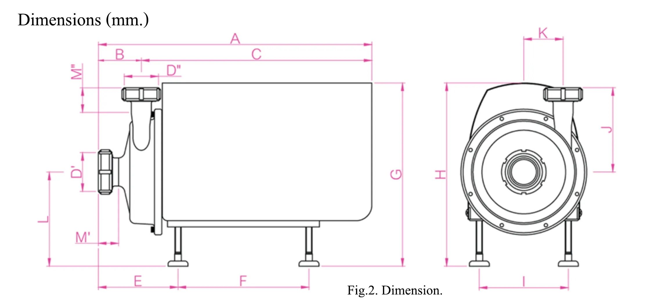
Dimensions are listed by motor configuration and use the lettered positions on the FCM drawing. Dimensions are in millimetres and weights are in kilograms.
Use the configuration-specific table when discussing equipment connections and installation space.
Discuss Your Utility Duty
Tell us whether the pump will handle water or hot water, the operating temperature, required flow rate and head or pressure, and the pipe connections and installation requirements.
Request FCM Pump Information
FEC and FCM Dimensions, Weights and Curve References
Reading the Dimensions
Dimensions are in millimetres. Lettered positions refer to the corresponding model drawing; they are not interchangeable with overall length, width or height. Weights are in kilograms and apply to the stated motor configuration.
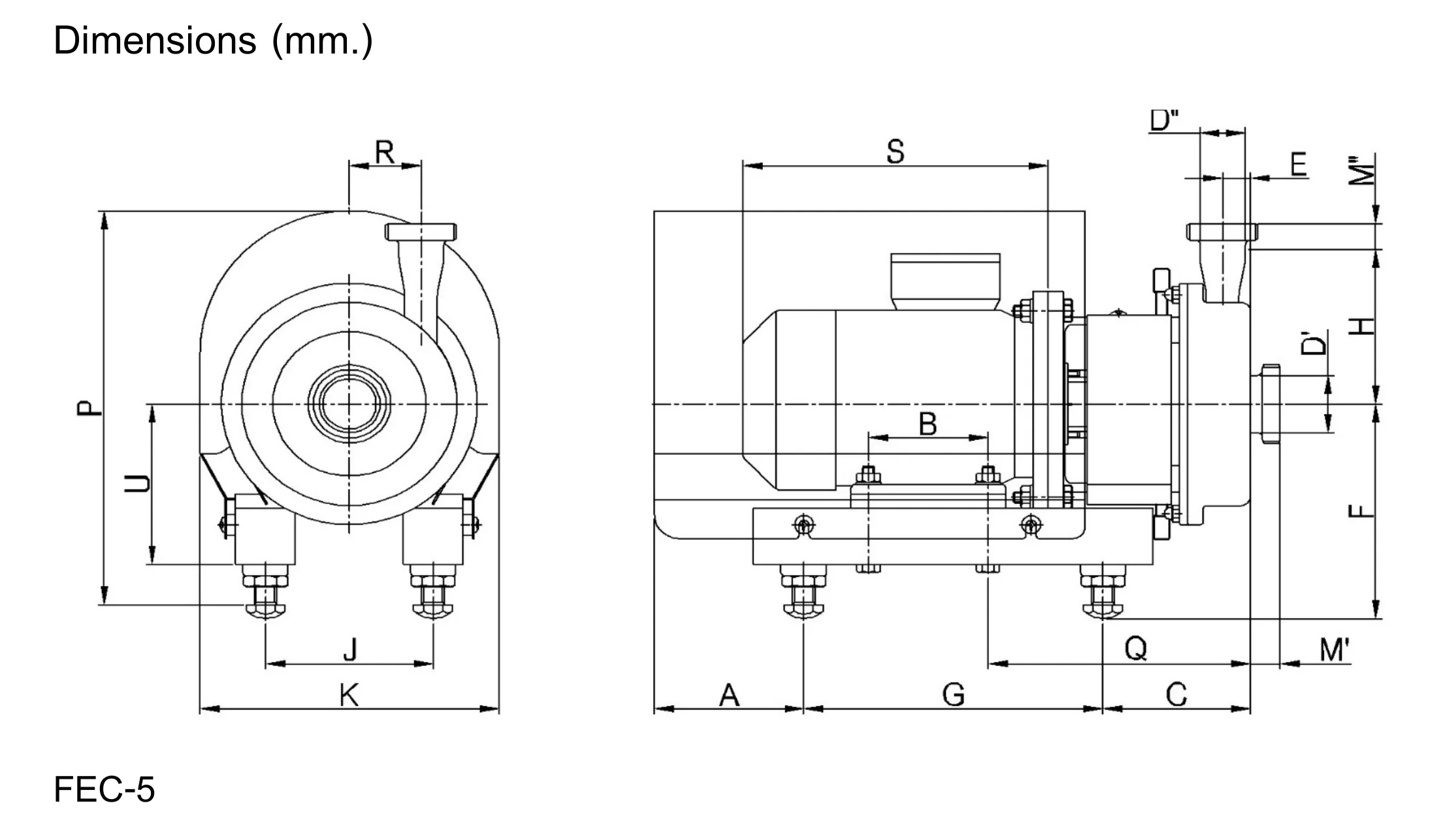
FEC 5 Dimensions
| Drawing reference (mm) | 0.55 kW | 0.75 kW |
|---|---|---|
| A | 125 | 125 |
| B | 100 | 100 |
| C | 123 | 123 |
| D′ | 50.8 | 50.8 |
| D″ | 38.1 | 38.1 |
| E | 23 | 23 |
| F min | 182 | 182 |
| F max | 217 | 217 |
| G | 250 | 250 |
| H | 137 | 137 |
| J | 140 | 140 |
| K | 250 | 250 |
| P min | 353 | 353 |
| P max | 388 | 388 |
| Q | 219 | 219 |
| R | 60 | 60 |
| S | 255 | 255 |
| U | 142 | 142 |
| M′ | 25 | 25 |
| M″ | 23 | 23 |
The listed dimensions apply to both 0.55 kW and 0.75 kW configurations.
FEC 5 Weights
| Motor configuration | Weight (kg) |
|---|---|
| 0.75 kW | 41.5 |
FEC 10 Dimensions
| Drawing reference (mm) | 0.75 kW | 1.1 kW | 1.5 kW | 2.2 kW | 3 kW | 4 kW |
|---|---|---|---|---|---|---|
| A | 80 | 80 | 80 | 80 | 120 | 120 |
| B | 125 | 125 | 125 | 125 | 140 | 140 |
| C | 132 | 132 | 132 | 132 | 110 | 110 |
| E | 21.5 | 21.5 | 21.5 | 21.5 | 21.5 | 21.5 |
| F min | 193 | 193 | 193 | 193 | 215 | 215 |
| F max | 231 | 231 | 231 | 231 | 254 | 254 |
| G | 305 | 305 | 305 | 305 | 360 | 360 |
| H | 145 | 145 | 145 | 145 | 145 | 145 |
| J | 140 | 140 | 140 | 140 | 190 | 190 |
| K | 220 | 220 | 220 | 220 | 300 | 300 |
| P min | 348 | 348 | 348 | 348 | 404 | 404 |
| P max | 386 | 386 | 386 | 386 | 440 | 440 |
| Q | 232 | 232 | 232 | 232 | 246 | 246 |
| R | 89.5 | 89.5 | 89.5 | 89.5 | 89.5 | 89.5 |
| S | 290 | 290 | 290 | 290 | 339 | 339 |
| U | 140 | 140 | 140 | 140 | 162 | 162 |
The 0.75 kW and 1.1 kW configurations share the listed dimensions of the 1.5 kW configuration. This dimensional match does not imply the same weight or performance.
FEC 25 Dimensions
| Drawing reference (mm) | 5.5 kW | 7.5 kW | 11 kW | 15 kW |
|---|---|---|---|---|
| A | 115 | 115 | 130 | 130 |
| B | 140 | 140 | 210 | 210 |
| C | 148 | 148 | 127 | 127 |
| E | 55 | 55 | 55 | 55 |
| F min | 247 | 247 | 275 | 275 |
| F max | 252 | 252 | 310 | 310 |
| G | 390 | 390 | 520 | 520 |
| H | 186 | 186 | 186 | 186 |
| J | 216 | 216 | 254 | 254 |
| K | 326 | 326 | 390 | 390 |
| P min | 476 | 476 | 532 | 532 |
| P max | 481 | 481 | 567 | 567 |
| Q | 318 | 318 | 337 | 337 |
| R | 101 | 101 | 101 | 101 |
| S | 390 | 390 | 505 | 505 |
| U | 192 | 192 | 220 | 220 |
FCM Dimensions
| Drawing reference (mm) | 0.75 kW | 1.1 kW | 1.5 kW | 2.2 kW | 3 kW | 4 kW |
|---|---|---|---|---|---|---|
| A | 470 | 470 | 510 | 510 | 570 | 570 |
| B | 70 | 70 | 70 | 70 | 70 | 70 |
| C | 360 | 360 | 400 | 400 | 460 | 460 |
| E | 140 | 140 | 140 | 140 | 140 | 140 |
| F | 250 | 250 | 250 | 250 | 290 | 290 |
| G | 350 | 350 | 350 | 350 | 415 | 415 |
| H | 260 | 260 | 260 | 260 | 327 | 327 |
| I | 170 | 170 | 170 | 170 | 220 | 220 |
| J | 150 | 150 | 150 | 150 | 150 | 150 |
| K | 75 | 75 | 75 | 75 | 75 | 75 |
The table lists selected drawing positions for each motor configuration.
FCM Weights
| Motor configuration | Weight (kg) |
|---|---|
| 0.75 kW | 18 |
| 1.1 kW | 19 |
| 1.5 kW | 22 |
| 2.2 kW | 24 |
| 3 kW | 36 |
| 4 kW | 44 |
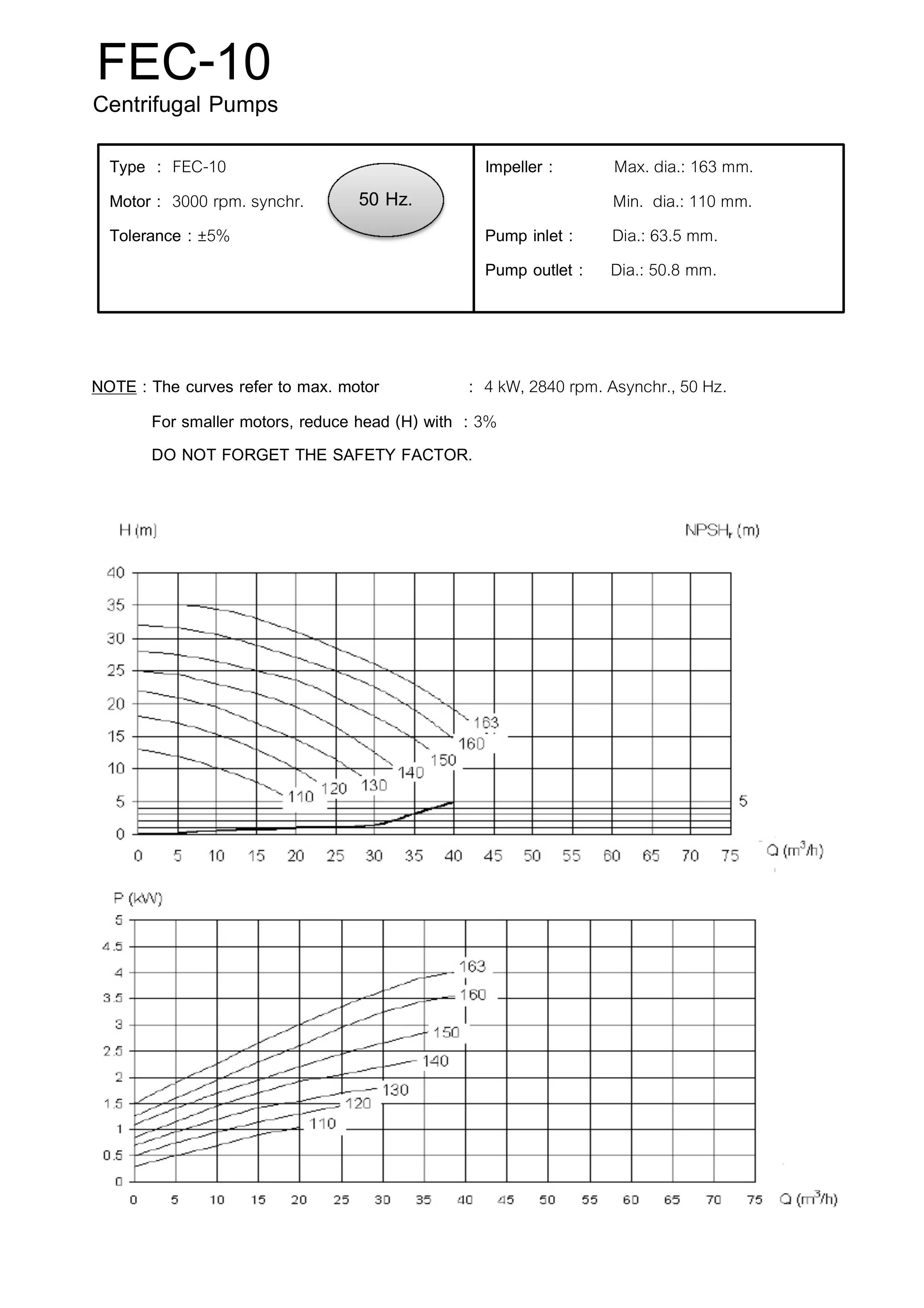
FEC 10 Reference Performance Curves
Reference configuration: 4 kW motor at 2,840 rpm asynchronous speed, 50 Hz. The reference states 3,000 rpm synchronous speed and impeller diameters from 110 to 163 mm.
Flow Q is expressed in m³/h, head H and required NPSH in metres, and power P in kW. The reference states a tolerance of ±5%, a 3% head reduction for smaller motors and consideration of a safety factor. These are conditions attached to this reference, not a performance guarantee for every available motor option.
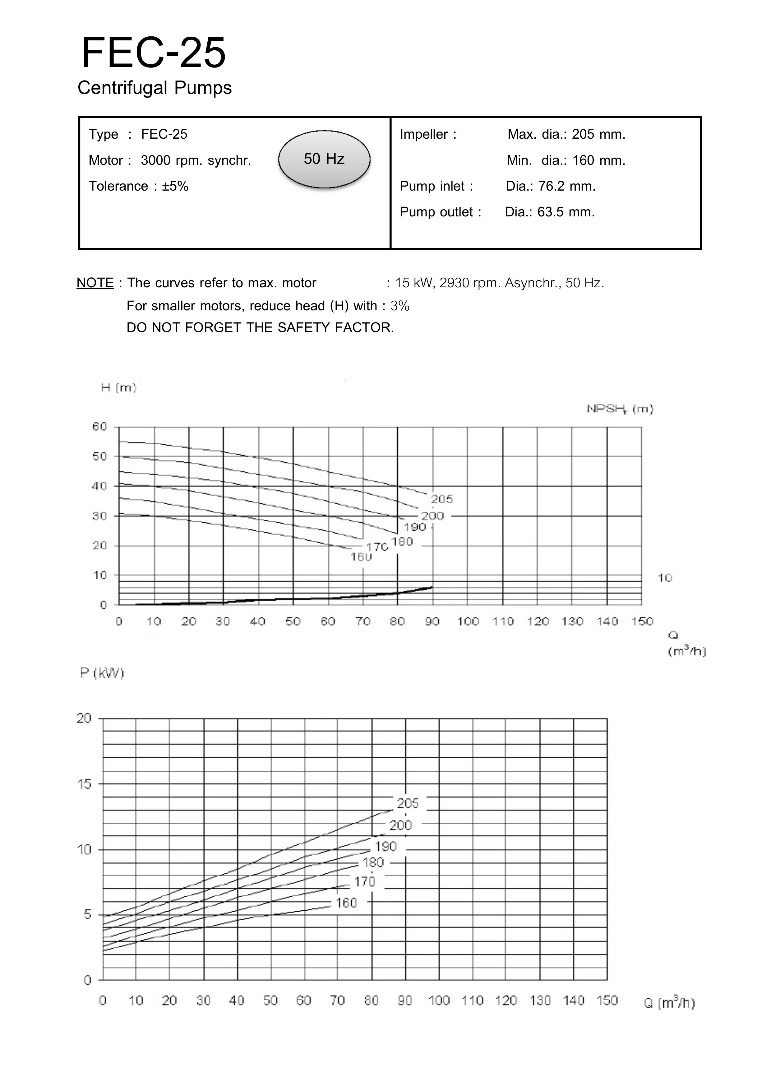
FEC 25 Reference Performance Curves
Reference configuration: 15 kW motor at 2,930 rpm asynchronous speed, 50 Hz. The reference states 3,000 rpm synchronous speed and impeller diameters from 160 to 205 mm.
Flow Q is expressed in m³/h, head H and required NPSH in metres, and power P in kW. The reference states a tolerance of ±5%, a 3% head reduction for smaller motors and consideration of a safety factor. These are conditions attached to this reference, not a performance guarantee for every available motor option.
Discuss the Required Duty
Provide the pump model and motor option under consideration, together with the liquid, required flow, head or pressure, and operating conditions. MNM can discuss the configuration appropriate to the application.
Discuss Fluid Handling Requirements
Dimension drawings and reference curves
Dimension (mm) and motor power (kW) refer to the selected configuration.
Use the lettered drawings with the dimension tables above. Curve conditions belong to the reference configuration shown.
FEC 5 Dimensions
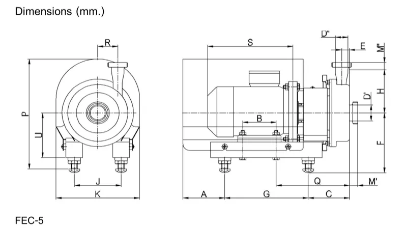
FEC 5 dimensional drawing and dimensions for the 0.55 and 0.75 kW configurations. Dimensions are in millimetres.
Contact Muninmax to confirm dimensions and connections for your configuration.
View full-size fec 5 dimensions
Scroll to view the full image. With a keyboard, Tab to the image area and use the arrow keys.
FEC 10 Dimensions
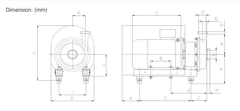
FEC 10 dimensional drawing and dimensions for the 0.75, 1.1, 1.5, 2.2, 3 and 4 kW configurations. Dimensions are in millimetres.
Contact Muninmax to confirm dimensions and connections for your configuration.
View full-size fec 10 dimensions
Scroll to view the full image. With a keyboard, Tab to the image area and use the arrow keys.
FEC 10 Reference Performance Curves
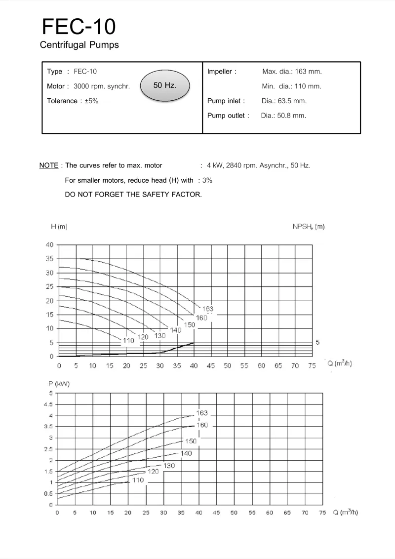
FEC 10 reference performance curves at 50 Hz, based on the source condition of a 4 kW motor at 2,840 rpm.
Reference configuration: 4 kW motor at 2,840 rpm asynchronous speed, 50 Hz. The reference states 3,000 rpm synchronous speed and impeller diameters from 110 to 163 mm. Flow Q is expressed in m³/h, head H and required NPSH in metres, and power P in kW. The reference states a tolerance of ±5%, a 3% head reduction for smaller motors and consideration of a safety factor. These are conditions attached to this reference, not a performance guarantee for every available motor option. The flow-axis label between 50 and 60 has been corrected to 55; the plotted curves are unchanged.
View full-size fec 10 reference performance curves
Scroll to view the full image. With a keyboard, Tab to the image area and use the arrow keys.
FEC 25 Dimensions
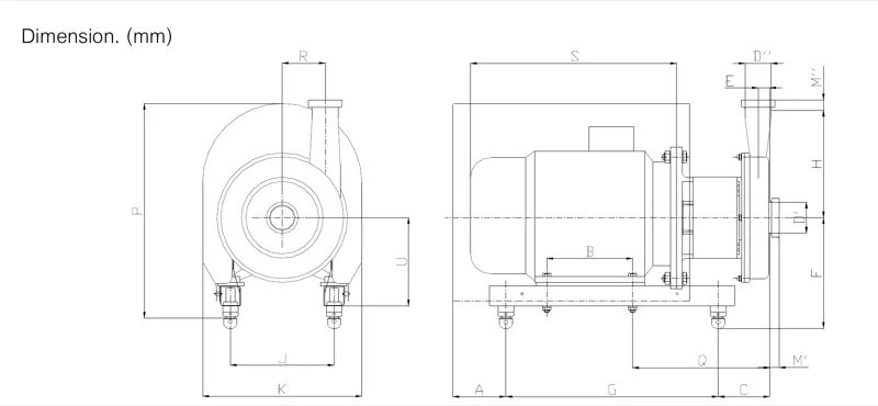
FEC 25 dimensional drawing and dimensions for the 5.5, 7.5, 11 and 15 kW configurations. Dimensions are in millimetres.
View full-size fec 25 dimensions
Scroll to view the full image. With a keyboard, Tab to the image area and use the arrow keys.
FEC 25 Reference Performance Curves
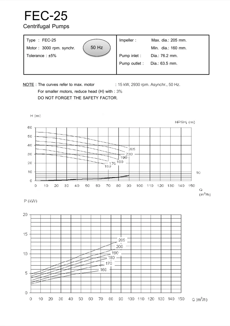
FEC 25 reference performance curves at 50 Hz, based on the source condition of a 15 kW motor at 2,930 rpm.
Reference configuration: 15 kW motor at 2,930 rpm asynchronous speed, 50 Hz. The reference states 3,000 rpm synchronous speed and impeller diameters from 160 to 205 mm. Flow Q is expressed in m³/h, head H and required NPSH in metres, and power P in kW. The reference states a tolerance of ±5%, a 3% head reduction for smaller motors and consideration of a safety factor. These are conditions attached to this reference, not a performance guarantee for every available motor option.
View full-size fec 25 reference performance curves
Scroll to view the full image. With a keyboard, Tab to the image area and use the arrow keys.
FCM Dimensions
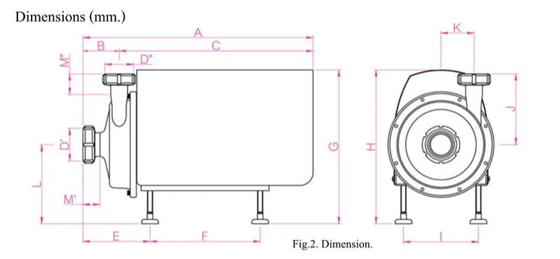
Selected FCM dimensions for 0.75, 1.1, 1.5, 2.2, 3 and 4 kW configurations. Dimensions are in millimetres; weights are in kilograms.
Contact Muninmax to confirm dimensions and connections for your configuration.
View full-size fcm dimensions
Scroll to view the full image. With a keyboard, Tab to the image area and use the arrow keys.