An aseptic filler fills prepared containers with sterilized product under controlled aseptic conditions. The filling system must be suited to the process and packaging.
Sterilized productFilling under controlled aseptic conditions.
Bag formats
Bin / Drum / BoxOn a supported model; 20 L refers to bag-in-box.
Upstream connection
UHT or aseptic tankAssessed for the product, process and project.
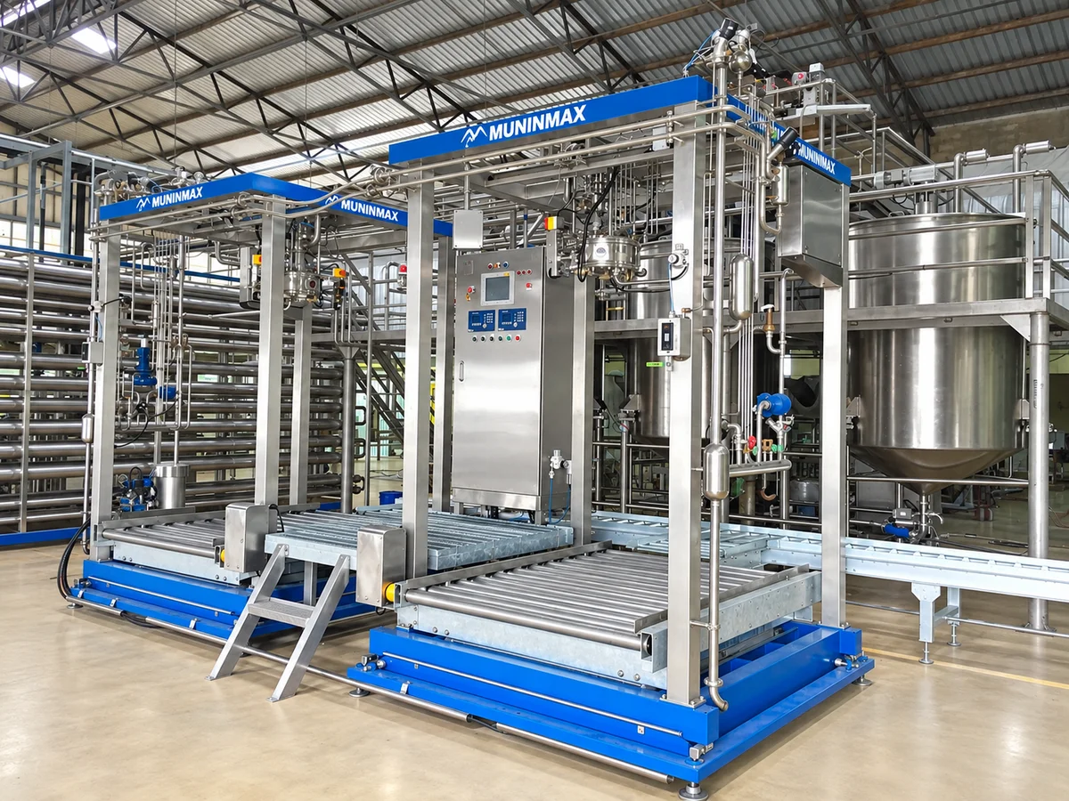
Aseptic filler — representative image.
Bag formats and machine options
Bag-in-bin
Bag-in-drum
20 L bag-in-box
Our aseptic fillers are intended for bulk filling into aseptic bags. We offer a model that supports aseptic bag-in-bin, bag-in-drum and 20 L bag-in-box formats on the same machine.
The bag type, bag connection and supporting container are specified for each project.
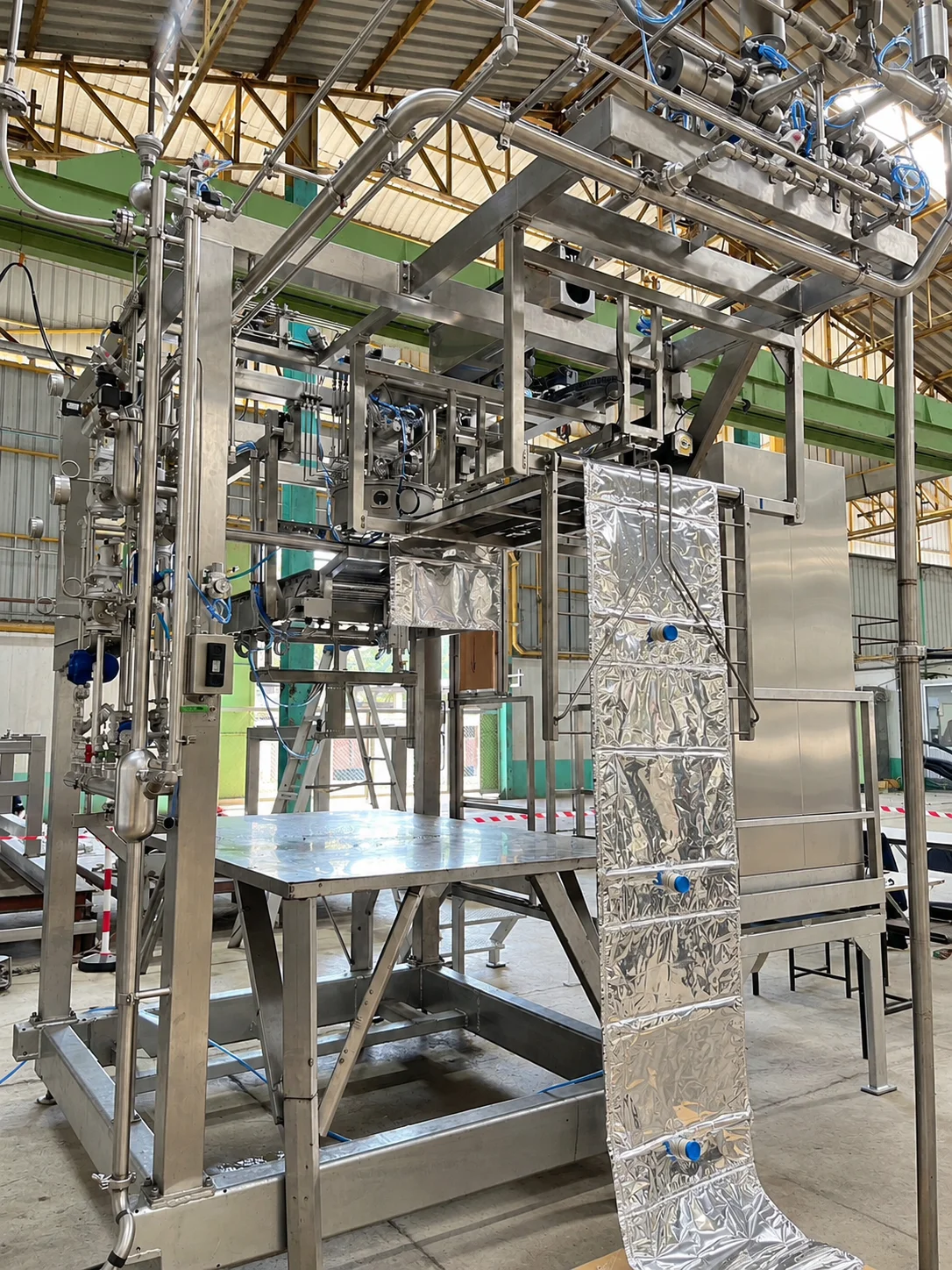
Filling assembly and laminate bag.
Selecting Equipment for the Bag Formats
Muninmax can configure an aseptic filler to handle bag-in-bin, bag-in-drum and bag-in-box formats on the same machine. The equipment arrangement is selected for the formats and operating requirements involved.
Drum and bin filling require an X-Lift. For drum filling, the X-Lift raises the drum to prevent excessive tension on the bag during filling. An Autofeed Bag System uses web bags, supplied as a continuous series of connected bags.
Compare the intended use and equipment arrangement for each configuration.
Bag formats and equipment arrangements
Intended use
Equipment arrangement
Bag-in-drum only
Include an X-Lift to raise the drum during filling.
Bag-in-box only
An X-Lift is not required and can be omitted. An Autofeed Bag System can be considered according to the operating requirements.
Drum and box
A small X-Lift can be used. An Autofeed Bag System can be added when box-filling volumes justify it, while avoiding the cost of a Big X-Lift where it is not needed.
Mainly drum filling, with a limited amount of box filling
Use the aseptic filler with an X-Lift and feed the bag-in-box bags manually.
Bin, drum and box
Select a Big X-Lift for the bins, which can also handle drums. An Autofeed Bag System can be added where box-filling volumes justify it.
The selected equipment and options are defined for the machine and project. Each configuration should be discussed against the intended bag formats and operating requirements.
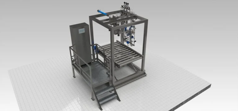
3D illustration of an aseptic filling equipment arrangement.
Sterilization approach and validation
Our aseptic filler uses steam together with hydrogen peroxide (H₂O₂) within the filling chamber as part of its sterilization system. During cap sterilization, the temperature inside the filling chamber does not exceed 100°C.
Process-authority testing has been carried out for a customer application. Supporting documentation is retained by the customer for audit purposes.
Under the operating conditions assessed, we have observed reduced visible steam plume and condensate compared with higher-temperature steam operation.
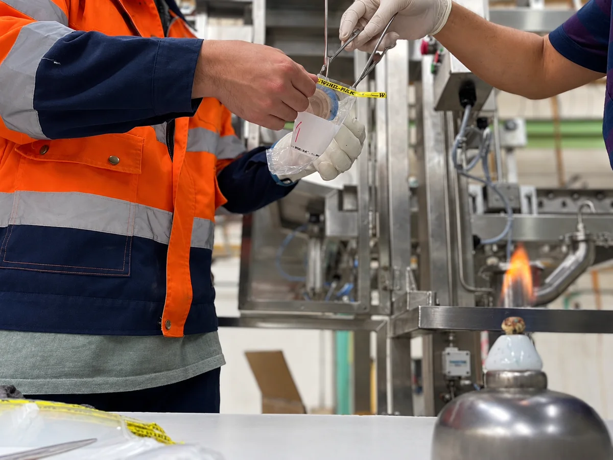
Sample handling near filling equipment.
Connection to the aseptic process
Our aseptic fillers can connect directly to a UHT system or to an aseptic tank, depending on the product, process and project requirements.
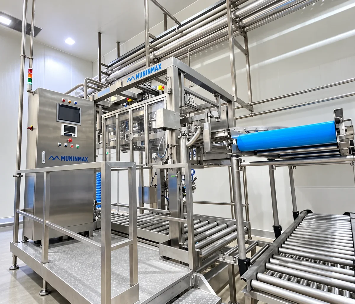
Aseptic Bulk Bag Fillers — aseptic filler head and roller-conveyor arrangement.
Designed and built by Muninmax
We design and fabricate our aseptic fillers in-house from stainless steel sheet and tubing. We also specify and source the associated equipment and components.
The filling system and its connections are designed around the product, packaging and project requirements.
Project scope and performance guarantees
Our services cover design, manufacture, procurement, installation, commissioning and after-sales service. Included work, optional items, exclusions and each party’s responsibilities are defined in the project proposal and agreement.
The machine and associated equipment are supplied according to the agreed delivery scope. Testing and acceptance criteria are agreed for each project.
Performance guarantees are agreed in writing for each project. They specify the guaranteed values, raw material and operating conditions, test methods and acceptance criteria.
Define the Bag and Container Together
Provide the intended bag format, bag connection and supporting container when discussing a format change. The required arrangement is assessed for the particular machine and packaging combination.
A supported format does not mean that every bag size, connection or spout position can be used without adjustments. The applicable parts and changes are determined for the machine being considered.
Include the Upstream Connection
Describe whether the filler will receive product directly from a UHT system or from an aseptic tank. The product, packaging and connections are considered together within the project scope.
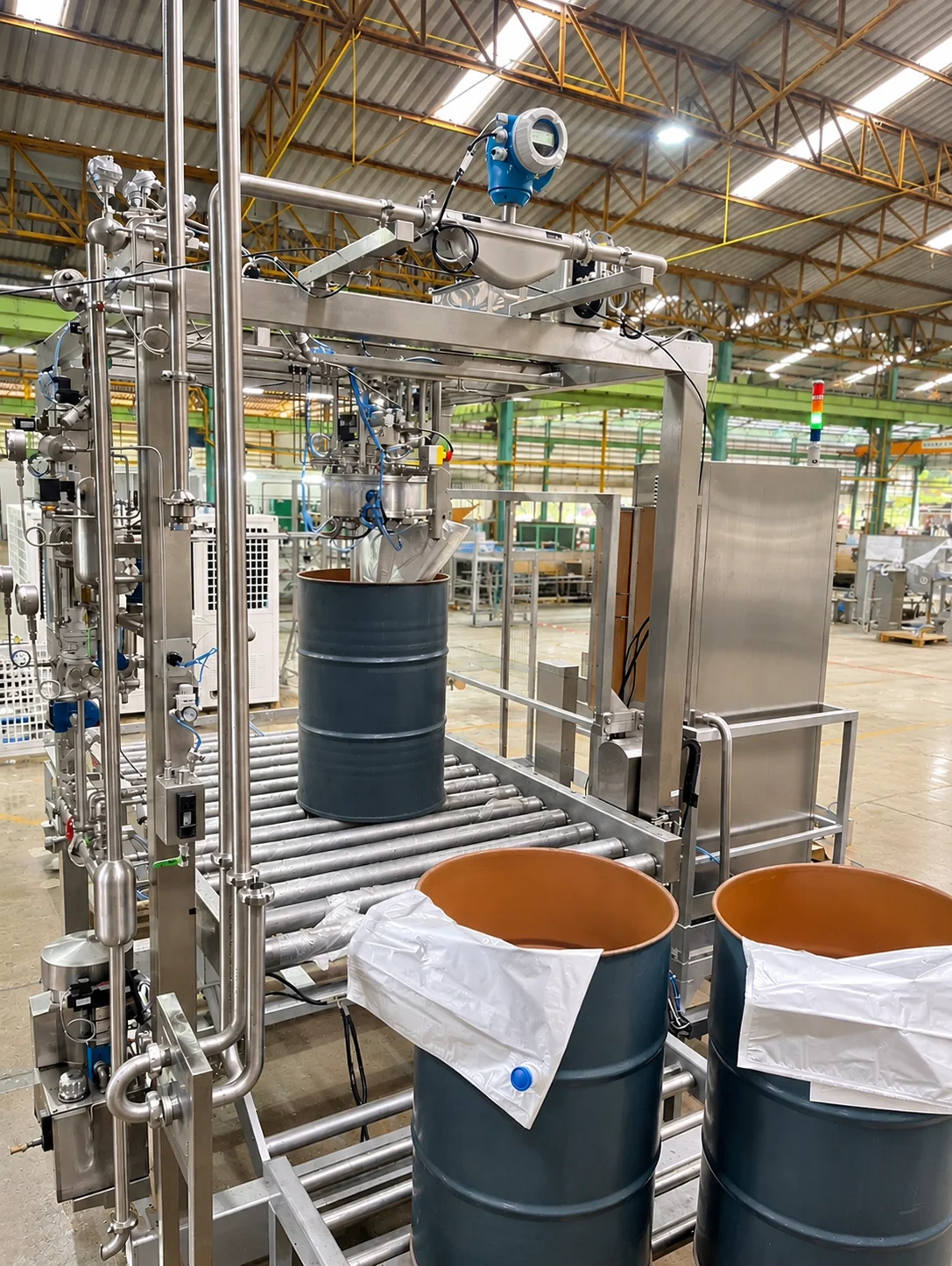
The single-head arrangement includes preparation, filling and CIP sequences, with operator involvement in setup and starting operations. The filling head can be adapted for bag caps up to 2 inches in size. Product-piece suitability is assessed with the product path and selected filling configuration.
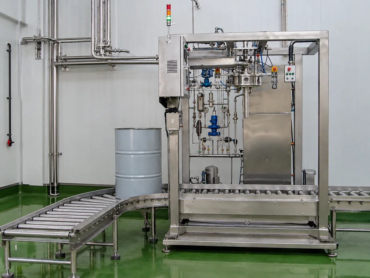
Aseptic Bulk Bag Fillers — single-station aseptic bulk filler configuration.
Equipment and Control Scope
Equipment and Control Scope — reference data
Item
Configuration
Filling arrangement
Single-head aseptic bulk bag filling
Bag cap adaptation
Up to 2 inches
Design and capacity
Defined by the project design criteria
Capacity selection factors
Bag size, product supply facilities and operator handling
Filling measurement
Electromagnetic or mass flow meter, or load cell, according to the design criteria
Product-contact metal parts
AISI 316L stainless steel
Machine controls
PLC and HMI included
Additional controls and system integration
Separate options
Electrical requirements
Specified according to the selected functions
Bag Handling and Options
The reference head arrangement provides clamps for 200 L or 1,000 L bags according to the configuration. Its roller conveyor has a 0.37 kW geared motor, and the hydraulic X-Lift system has a 1.1 kW rating. These are component ratings for that arrangement.
An automatic bag-feed system for connected web bags is an option. Preparing the first bag of each carton still requires operator action. Bag formats, clamps, lift arrangement and automatic feeding are selected together for the intended operation.
Reference Utility Requirements
The following values describe the single-head reference configuration. Final utility requirements follow the selected equipment and operating functions. Pressure values marked kPa(e) are gauge pressures.
Reference Utility Requirements — reference data
Utility
Reference requirement
Steam pressure
500–700 kPa(e)
Steam back pressure
No more than 100 kPa(e)
Steam consumption per head
16 kg/h during filling; 40 kg/h during sterilization
Compressed air pressure
600–800 kPa(e)
Compressed air dew point
No higher than −3°C
Compressed air flow
2 m³/h per head
Reference electrical supply
380 V / three-phase / 50 Hz
Chilled water
1 L/min at 1 barg and 7–15°C per head
Process-water quality
Drinking-water grade
Process-water supply
300–400 kPa(e), 20–35°C
Process-water flow during start-up and SIP
8 m³/h
The steam rates describe different operating phases. Water required during start-up and SIP is identified separately from continuous production use. Cleaning connections are designed around the customer's central CIP supply.
Bag Formats and Handling Options
Drum and bin filling require an X-Lift. For drum filling, the lift raises the drum to avoid excessive bag tension. An Autofeed Bag System uses connected web bags.
Bag Formats and Handling Options — reference data
Intended formats
Arrangement to discuss
Bag-in-drum only
X-Lift for drum filling
Bag-in-box only
X-Lift can be omitted; Autofeed can be considered
Drum and box
Small X-Lift; Autofeed where box-filling volumes justify it
Mainly drums with limited box filling
X-Lift with manual bag-in-box feeding
Bin, drum and box
Big X-Lift for bins and drums; optional Autofeed for box filling
A supported format does not mean that every bag size, connection or spout position can be used without adjustments. Equipment and changes are defined for the selected machine and packaging.
Upstream Connection
The filler can receive product directly from a UHT system or through an aseptic tank. Product, packaging, tank connections and control integration are considered together.
Discuss Your Filling Arrangement
Share the product and particle characteristics, bag size and connection, supporting container, product supply and required filling rate. Include the intended tank connection and control integration.