
Product concentration
Evaporation Systems
Liquid concentration systems designed around your product and production requirements
Muninmax designs and manufactures evaporation systems for liquid-product concentration, including pineapple juice and coconut water.
Our offering includes multi-effect falling film long tube evaporators and forced circulation systems. For final-stage concentration, MNM offers both falling film and forced circulation Finishers, selected according to product viscosity, flow behaviour and concentration requirements.
Each system is designed around the incoming product, production duty, target concentration and available plant utilities.
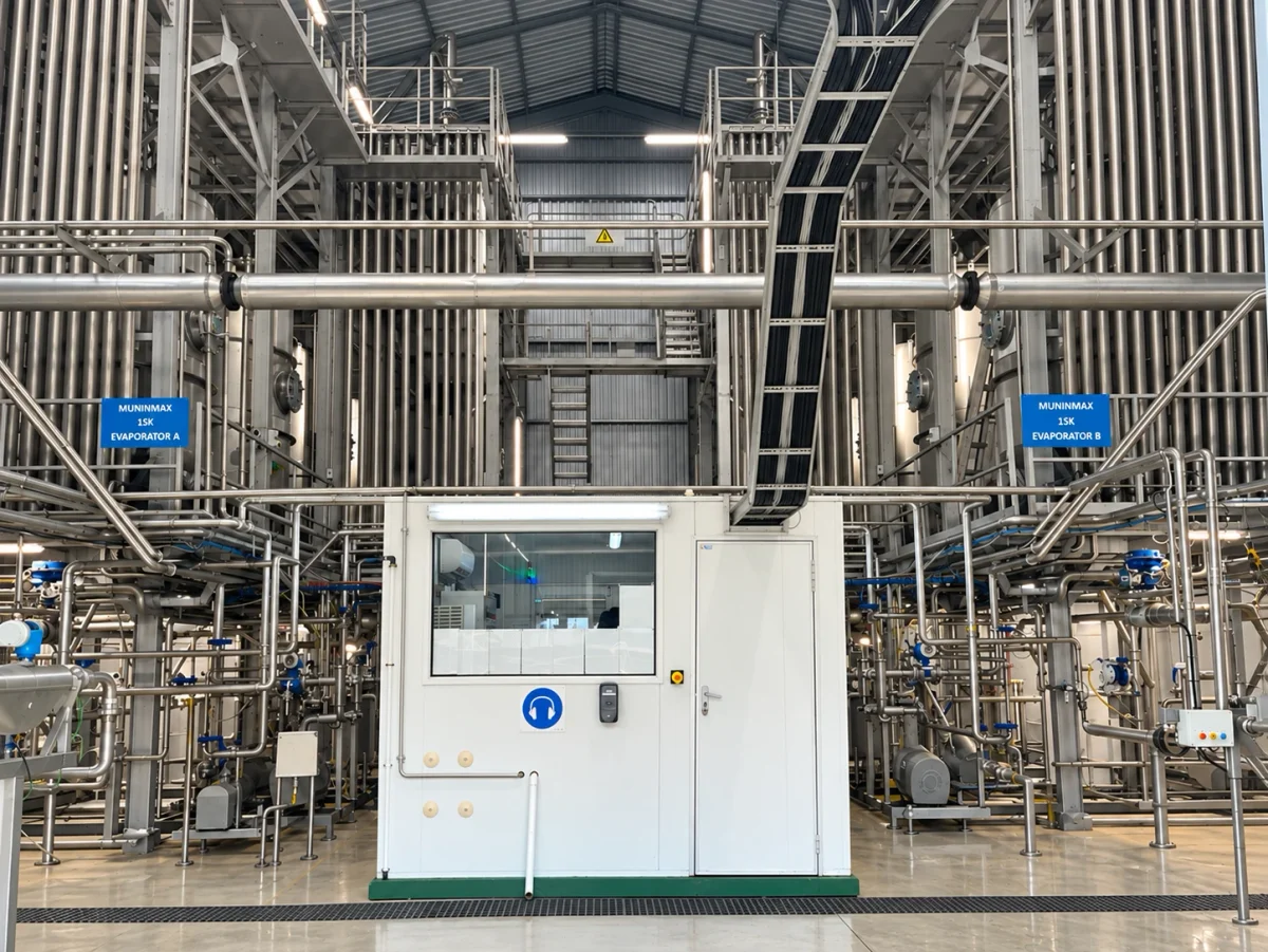
- MNM Falling Film
- 2–6 effectsSelected for the product, duty and utilities.
- Finisher options
- Falling Film or FCSelected for viscosity and flow behaviour.
- Energy configurations
- Multiple effects · TVR · MVREvaluated for each project.
01 / Evaporation
Applications & Industries
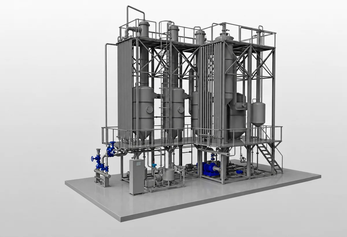
MNM Applications: Pineapple Juice & Coconut Water
MNM designs and manufactures systems for concentrating pineapple juice and coconut water.
The evaporator forms part of the complete processing line. Feed conditions and concentrate outlet requirements are coordinated with upstream preparation and downstream treatment, storage or filling.
| Application | Feed to the evaporation stage | Concentrated product |
|---|---|---|
| Pineapple juice concentration | Pineapple juice prepared by the upstream process | Pineapple juice concentrate for subsequent processing |
| Coconut water concentration | Coconut water prepared by the upstream process | Coconut water concentrate for subsequent processing |
Turning liquid products into concentrates
Evaporation removes part of the water from a liquid product to increase its concentration. The process prepares concentrates, adjusts solids content and produces ingredients for further processing.
For example, pineapple juice enters an evaporation system as a liquid feed. As water is removed, the remaining juice becomes more concentrated. The final concentration forms part of the product and process design.
Product composition, viscosity, heat sensitivity and concentration requirements influence the equipment arrangement and operating conditions.
Where Evaporation Is Used
The following examples illustrate applications across food and beverage processing.
| Industry | Example products | Application focus |
|---|---|---|
| Fruit Juice & Coconut Water | Pineapple, apple and citrus juice concentrates; coconut water concentrate | Starting and target concentrations, pulp content and downstream requirements |
| Dairy Products | Milk and whey concentrates | Product composition, heat sensitivity and viscosity changes |
| Tea, Coffee & Food Extracts | Concentrated tea, coffee and other food extracts | Extract composition, concentration target and temperature constraints |
| Sugar & Food Ingredients | Concentrated sugar solutions and glucose syrups | Solids concentration, viscosity and behaviour during concentration |
02 / Evaporation
Understanding Evaporator Types
Evaporators differ in how the product moves across the heating surface, where evaporation occurs and how liquid and vapour are separated.
Viscosity, heat sensitivity, solids content and deposit formation help determine the appropriate arrangement.
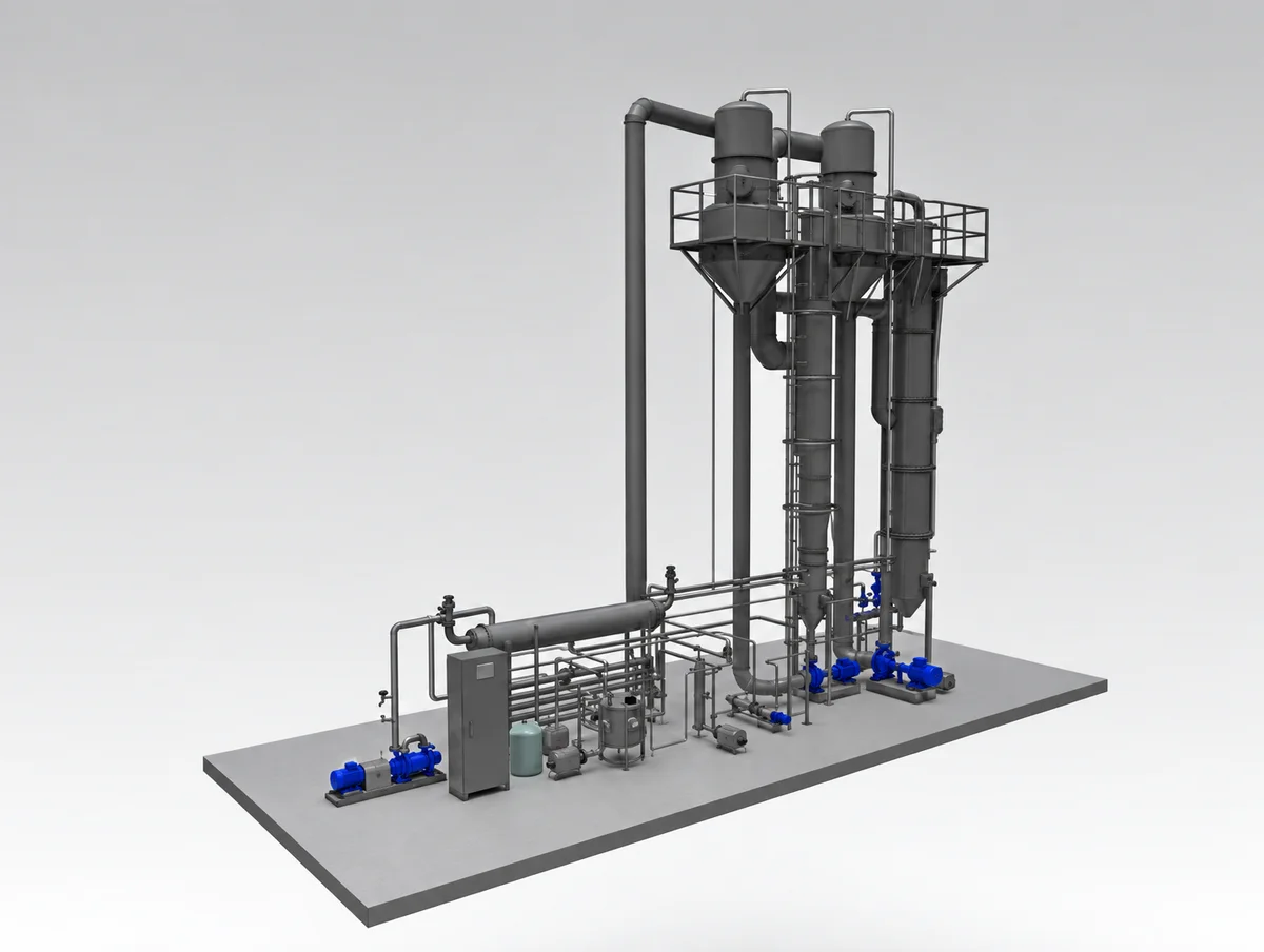
Falling Film Evaporators
Product flows downward as a thin film along heated surfaces. In tubular systems, the liquid travels along the inside walls of vertical tubes.
Falling film evaporation is widely used for heat-sensitive liquids. Relatively short residence time supports control of thermal exposure, while uniform product distribution and surface wetting remain essential design considerations.
A falling film arrangement can perform the main evaporation duty or serve as a Finisher when the concentrate maintains suitable flow and film formation at the required finishing conditions.
Forced Circulation Evaporators
A pump circulates product through a heat exchanger and separation vessel.
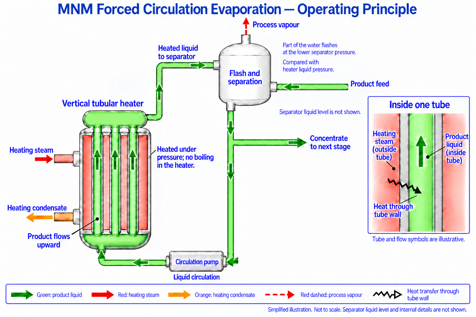
In a typical flash-type arrangement, pressure prevents boiling inside the heat exchanger. The heated product then enters a lower-pressure separator, where part of its water flashes into vapour. Liquid returns through the circulation loop while concentrate is withdrawn.
Forced circulation is suited to duties involving higher viscosity, deposit-forming products or demanding final-concentration conditions. It can serve as the main evaporation system or as a Finisher. Circulation rate, pump duty and temperature exposure are considered together.
Plate Evaporators
Plate evaporators transfer heat through plates separating the product and heating-medium channels. Some use a rising-film arrangement, with generated vapour helping carry liquid upward.
They provide an alternative construction for concentration duties, including sugar solutions and selected food liquids. Plate geometry, channel suitability, installation space and cleaning access influence selection.
“Plate” describes the heat-transfer construction; “rising film” or “falling film” describes the flow arrangement.
Comparing the Arrangements
| Consideration | Tubular Falling Film | Forced Circulation | Plate Evaporator |
|---|---|---|---|
| Product movement | Thin film flowing down heated tubes | Pump-driven circulation through a heating and separation loop | Flow through channels between plates |
| Main design focus | Distribution and surface wetting | Circulation conditions and separation duty | Plate geometry and channel arrangement |
| Selection factors | Heat sensitivity, viscosity and ability to maintain a liquid film | Viscosity, circulation requirements and concentration duty | Product properties, channel suitability and installation requirements |
These descriptions introduce the technologies. MNM’s falling film and forced circulation configurations are detailed below.
03 / Evaporation
MNM Falling Film Evaporators
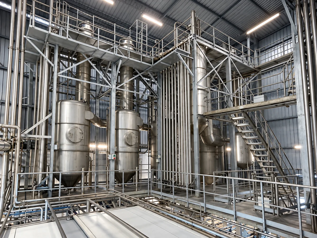
Multi-effect concentration with two to six effects
MNM designs and manufactures multi-effect falling film long tube evaporators with two to six effects.
The selected arrangement follows the product, water-removal duty, production requirements and available utilities.
How Falling Film Evaporation Works
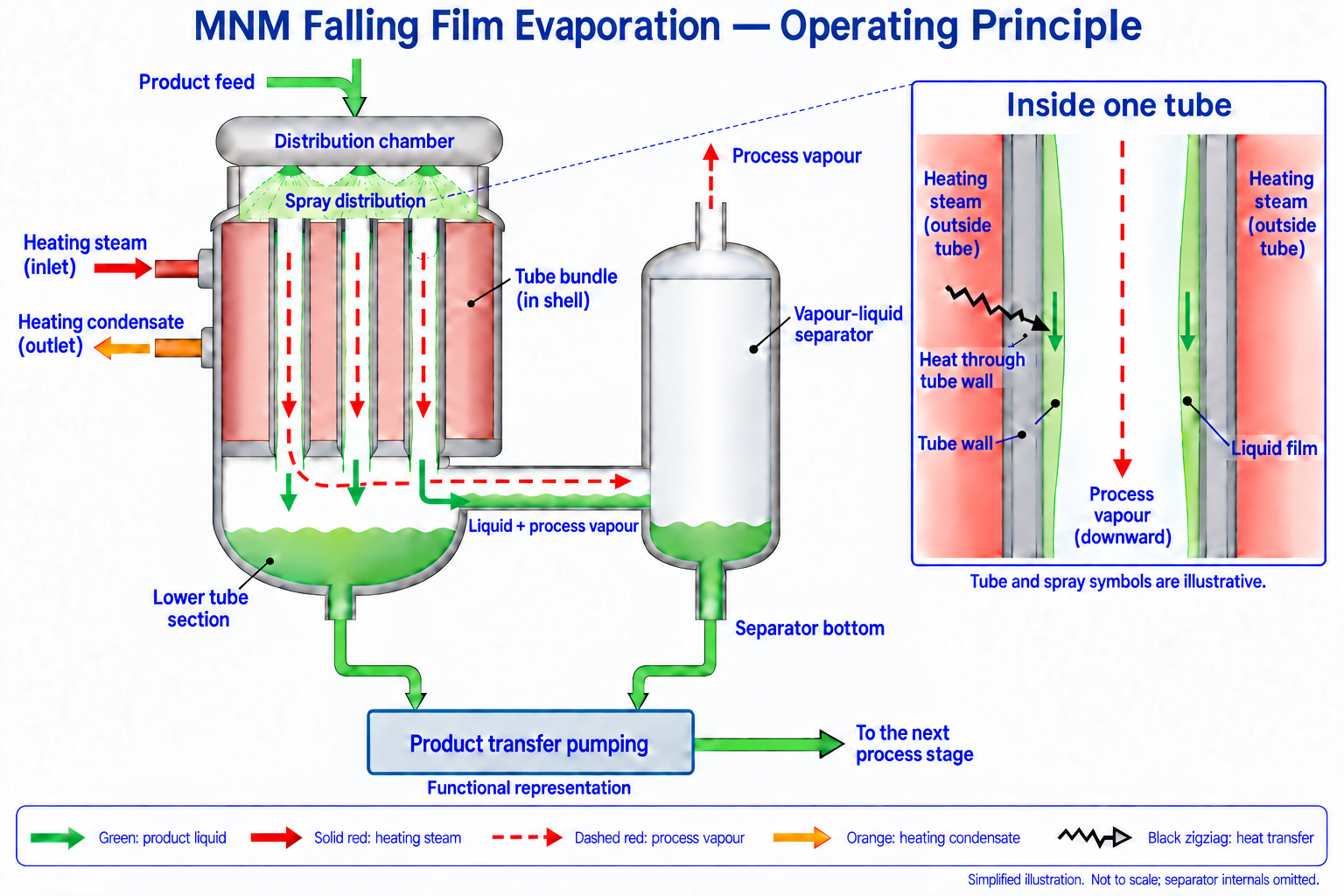
- Product enters the distribution section. Liquid enters at the top and is distributed over the inside surfaces of the heating tubes.
- A thin film flows down the tubes. Uniform distribution keeps the heating surface wetted as the liquid travels downward.
- Heat passes through the tube walls. Steam outside the tubes supplies heat, evaporating part of the water in the product. Heating steam and product remain in separate flow paths.
- Vapour and concentrate are separated. Generated vapour leaves through its own outlet, while concentrated liquid is collected for the following stage.
- Concentration continues through the selected arrangement. In a multi-effect system, vapour generated in one effect supplies heat to another.
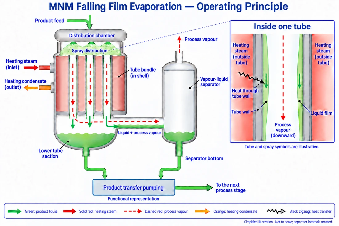
Product is spray-distributed into the heating tubes and flows downward as a thin film. Heat passes through the tube walls, evaporating part of the water. Liquid and process vapour enter a side separator, while liquid collected from the lower tube section and separator is transferred onward without recirculation to the same tube bundle during normal production.
Simplified illustration of the MNM arrangement described here. Not to scale; internal separator details are omitted.
View full-size falling film operating principle
Tab to the image area and use the arrow keys to read the full diagram. Tab again to leave the area.
Falling Film for Final-Stage Concentration
MNM also offers falling film Finishers for products that maintain suitable distribution and film flow during final concentration.
Selection considers the concentrate entering the finishing stage and how its viscosity changes as more water is removed. The product must maintain appropriate flow and heating-surface wetting through to the required final condition.
Materials, Construction & Controls
| Item | MNM Falling Film Evaporator specification basis |
|---|---|
| Main configuration | Multi-effect falling film long tube |
| Number of effects | Two to six, selected for the project |
| Product-contact metal parts | AISI 316L stainless steel as standard |
| Product-contact elastomer seals and O-rings | Selected for the product and operating conditions |
| Evaporator control | PLC and HMI included as standard |
| Integration with other control systems | Defined for the project |
| Support structure | Materials selected for structural loading |
Support construction uses galvanized carbon steel where heavier loads call for it. AISI 304 stainless steel can be used for lighter-duty support components, according to the structural design.
Feed supply and concentrate discharge are coordinated with the preceding and following processes. Where a separate finishing stage is required, its configuration is selected for the concentrate and final production target.
04 / Evaporation
MNM Forced Circulation Evaporators
Main evaporation and final concentration, configured for the process
MNM forced circulation evaporators can serve as the main concentration system or as an FC Finisher following another evaporator.
A circulation pump moves product through the heat-transfer section. Selection follows the product characteristics, incoming concentration, required production duty and final concentration target.
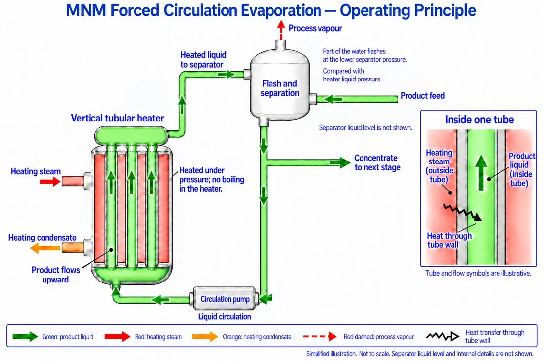
Fresh product enters the lower side of the separator tank, positioned above the heater. Liquid leaves the separator through a common outlet pipe, which branches into the circulation path and the concentrate outlet. A circulation pump moves the recirculating liquid upward through the tubes of a vertical heater. Steam on the separate shell side transfers heat through the tube walls. The heated liquid returns to the separator, where the lower pressure allows part of its water to flash into vapour. Concentrate is drawn from the shared outlet pipe and sent to the next process stage.
Simplified illustration of the MNM arrangement described here. Not to scale. Separator liquid level and internal details are not shown.
View full-size forced circulation operating principle
Tab to the image area and use the arrow keys to read the full diagram. Tab again to leave the area.
Product Circulation and Production Throughput
The circulation flow maintains product movement through the heat-transfer section.
This internal flow is different from the feed entering the system or the concentrate leaving it. Circulation requirements serve the heat-transfer duty; feed and concentrate flows define production throughput.
Two Roles in the Processing Line
| Consideration | Main FC Evaporator | FC Finisher |
|---|---|---|
| Position | Main evaporation stage | After the main evaporator |
| Incoming product | Feed prepared by the upstream process | Product already concentrated in the main evaporator |
| Assigned duty | Main water-removal and concentration duty | Further concentration to the required final condition |
| Design focus | Feed characteristics, throughput and concentration target | Incoming concentrate, viscosity and final-concentration requirement |
| Downstream connection | Defined by the next process | Defined by the next process |
Main evaporation arrangement
Upstream Process → FC Evaporator → Concentrate → Next Process
FC finishing arrangement
Main Evaporator → FC Finisher → Final Concentrate → Next Process
Selecting the FC Arrangement
Forced circulation supports duties involving particularly viscous products. Where a plant processes different products, the configuration is evaluated against the incoming condition and final requirement of each product.
Equipment dimensions, circulation requirements, heat-transfer duty and utilities are established for the assigned application.
“Forced circulation” describes the movement of product through the evaporation loop. “Finisher” describes the equipment’s role at the end of the concentration process. MNM selects either falling film or forced circulation for that finishing role according to the product and duty.
05 / Evaporation
Finishing & Energy Configurations
Finishing equipment and energy arrangements serve different purposes within the evaporation system.
A Finisher provides a dedicated final concentration stage and can use either falling film or forced circulation. TVR and MVR recover energy from process vapour for reuse in evaporation.
Finisher — Final Concentration Matched to Product Viscosity
A Finisher receives concentrate from the preceding evaporation stage and increases its concentration to the required final level before transfer to the next process.
MNM offers both falling film and forced circulation configurations for this duty. Selection considers the product’s viscosity and flow behaviour throughout the finishing stage.
Falling Film Finisher
A falling film configuration is selected when the concentrate can be distributed evenly and maintain a continuous liquid film over the heating surface.
Product viscosity and its change during concentration are important to maintaining suitable flow and surface wetting.
Forced Circulation Finisher
A forced circulation configuration uses a pump to circulate product through the heat-transfer section.
It is suited to more viscous concentrates where pump-driven circulation provides the appropriate product movement for the finishing duty.
How Viscosity Influences Selection
MNM considers the incoming concentrate, its viscosity at operating temperature, the target concentration and the required throughput.
Selection accounts for product behaviour throughout the finishing stage, including conditions near the final concentration.
The final concentration value alone does not determine the Finisher type. Products with similar solids concentrations can have different viscosities and require different equipment arrangements.
| Selection consideration | Falling Film Finisher | FC Finisher |
|---|---|---|
| Product movement | A distributed liquid film flows over the heating surface | A pump circulates product through the heat-transfer section |
| Viscosity consideration | The concentrate must maintain suitable distribution and film flow | Pump-driven circulation is selected to suit more viscous product conditions |
| Important design check | Surface wetting throughout the finishing duty | Circulation and heat-transfer requirements throughout the finishing duty |
Finishing arrangement
Main Evaporator → Falling Film or FC Finisher → Final Concentrate → Downstream Process
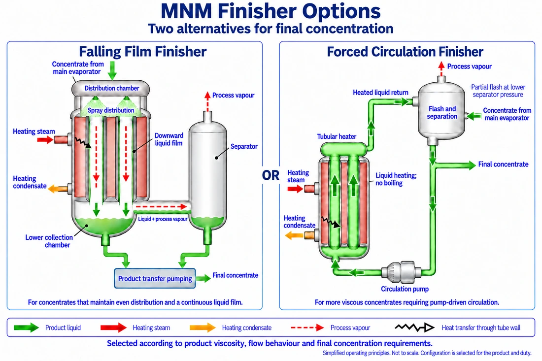
A Finisher receives concentrate from the main evaporator and raises it to the required final concentration. MNM offers falling film and forced circulation alternatives for this duty. Falling film relies on even product distribution and a continuous film over the heating surface. Forced circulation uses a pump to move product through the heater and back to the separator. Selection considers viscosity at operating conditions, flow behaviour throughout concentration and the required final duty. The two configurations shown are alternatives, not mandatory consecutive stages.
Simplified operating principles. Not to scale. Configuration is selected for the product and duty.
View full-size finisher alternatives
Tab to the image area and use the arrow keys to read the full diagram. Tab again to leave the area.
06 / Evaporation
Energy Options
Selecting the Number of Effects
An effect is an evaporation stage within the overall thermal arrangement. Multiple effects allow heat to be reused across the system.
MNM selects the number of effects by considering the product’s temperature constraints, evaporation duty, available utilities, production capacity and operating hours.
Increasing the number of effects can reduce steam consumption, while requiring consideration of additional heat-transfer area and investment. TVR or MVR can also be evaluated as part of the energy design.
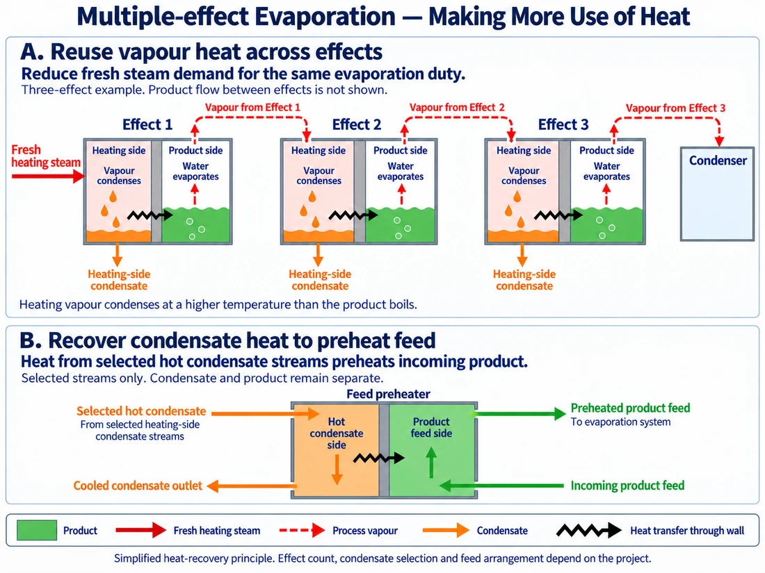
Multiple-effect evaporation reuses vapour generated in one effect to heat the next, reducing fresh steam demand for the same evaporation duty. Vapour condenses on the heating side while water evaporates from the product across a separating wall. Selected hot condensate streams can supply additional heat to a feed preheater: condensate leaves cooler, while incoming product leaves warmer. The two liquids remain separate. Three effects are illustrated; product routing between effects and the choice of condensate streams are project-specific.
Simplified heat-recovery principle. Effect count, condensate selection and feed arrangement depend on the project.
View full-size multiple-effect heat recovery
Tab to the image area and use the arrow keys to read the full diagram. Tab again to leave the area.
Supporting arrangement — 3D illustration
Forward and Backward Feed
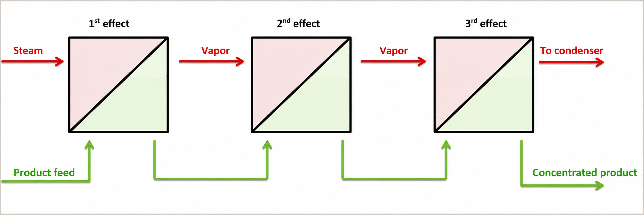
Forward Feed
Product moves from effect 1 to effect 2 and then to effect 3, in the same direction as the heating vapor.
View the forward feed arrangement
View full-size forward feed diagram
Tab to the image area, then use arrow keys. Tab again to leave.
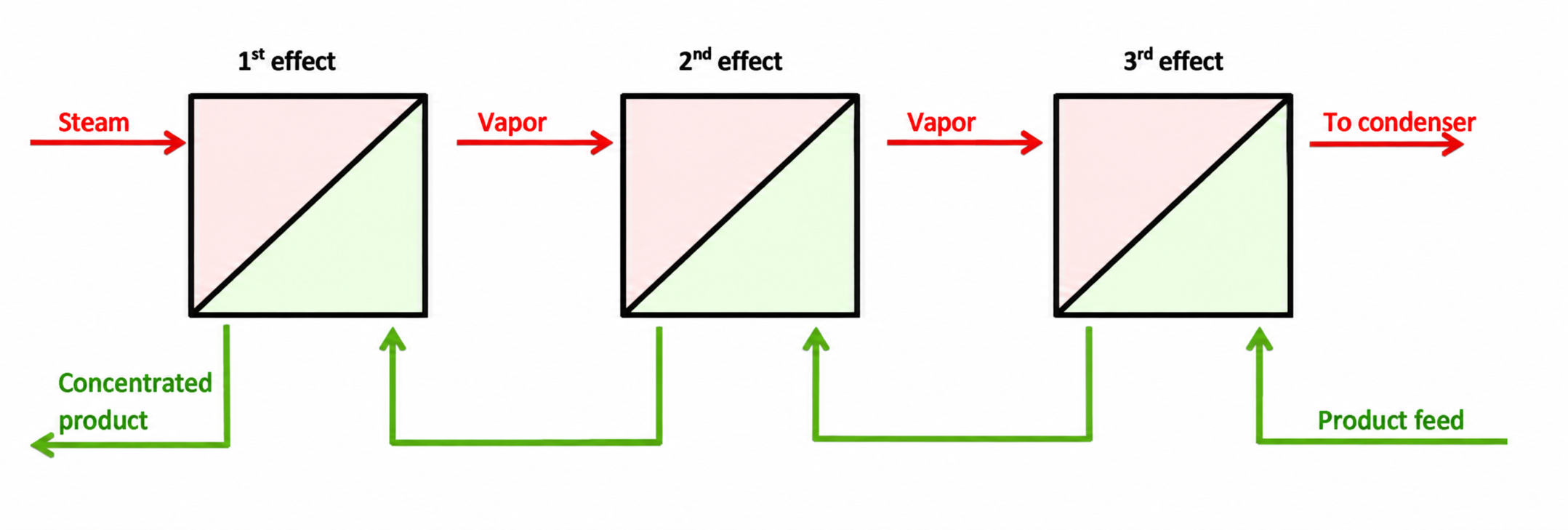
Backward Feed
Product moves from effect 3 to effect 2 and then to effect 1, while the heating vapor moves from effect 1 toward effect 3.
View the backward feed arrangement
View full-size backward feed diagram
Tab to the image area, then use arrow keys. Tab again to leave.
TVR — Thermal Vapour Recompression
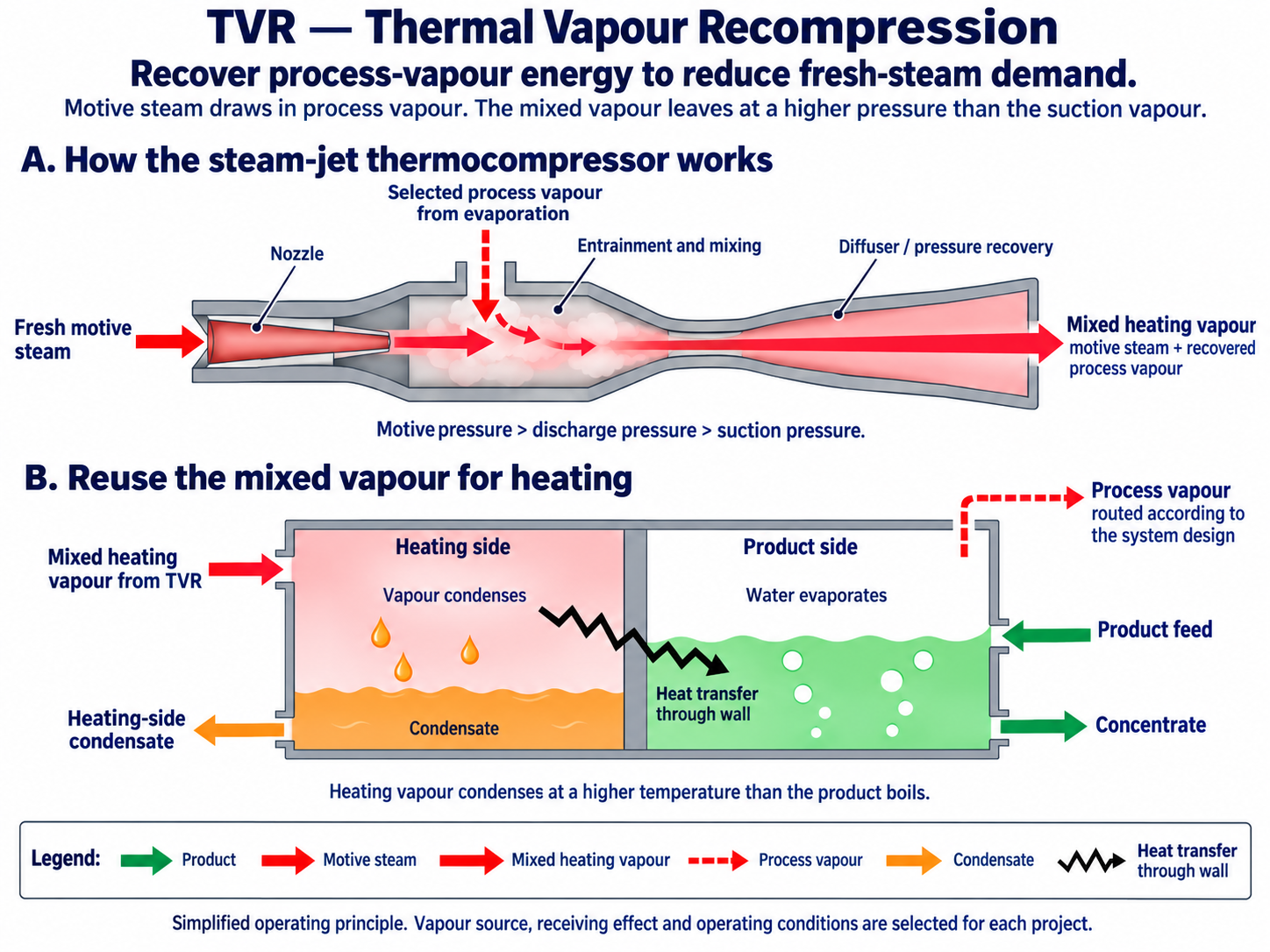
TVR uses motive steam to drive a steam-jet thermocompressor. It draws in part of the process vapour and raises its pressure for reuse as a heating medium.
Selection considers the available steam conditions and evaporation duty, with the aim of reducing fresh-steam demand through vapour-energy recovery.
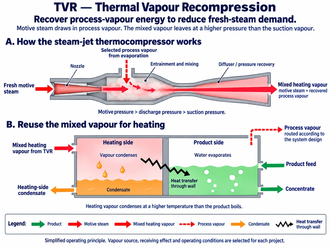
TVR uses motive steam to entrain a selected portion of process vapour. The two streams mix in a steam-jet thermocompressor, and the diffuser recovers pressure. The mixed discharge has a higher pressure than the suction vapour and supplies heat on the evaporator's heating side. It condenses while transferring heat through a separating wall to the product. Vapour-energy recovery reduces fresh-steam demand, while motive steam remains an external input. The vapour source and receiving effect depend on the system design; they need not be the same effect.
Simplified operating principle. Vapour source, receiving effect and operating conditions are selected for each project.
View full-size tvr operating principle
Tab to the image area and use the arrow keys to read the full diagram. Tab again to leave the area.
MVR — Mechanical Vapour Recompression
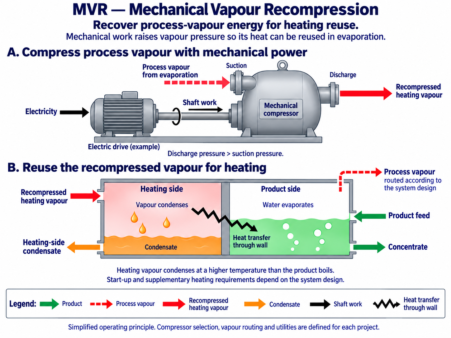
MVR uses a mechanically driven compressor, typically powered by electricity, to raise process-vapour pressure and temperature for heating reuse.
MNM evaluates the evaporation duty, electrical supply, utility costs and operating hours. Start-up or supplementary steam requirements are determined for the selected arrangement.
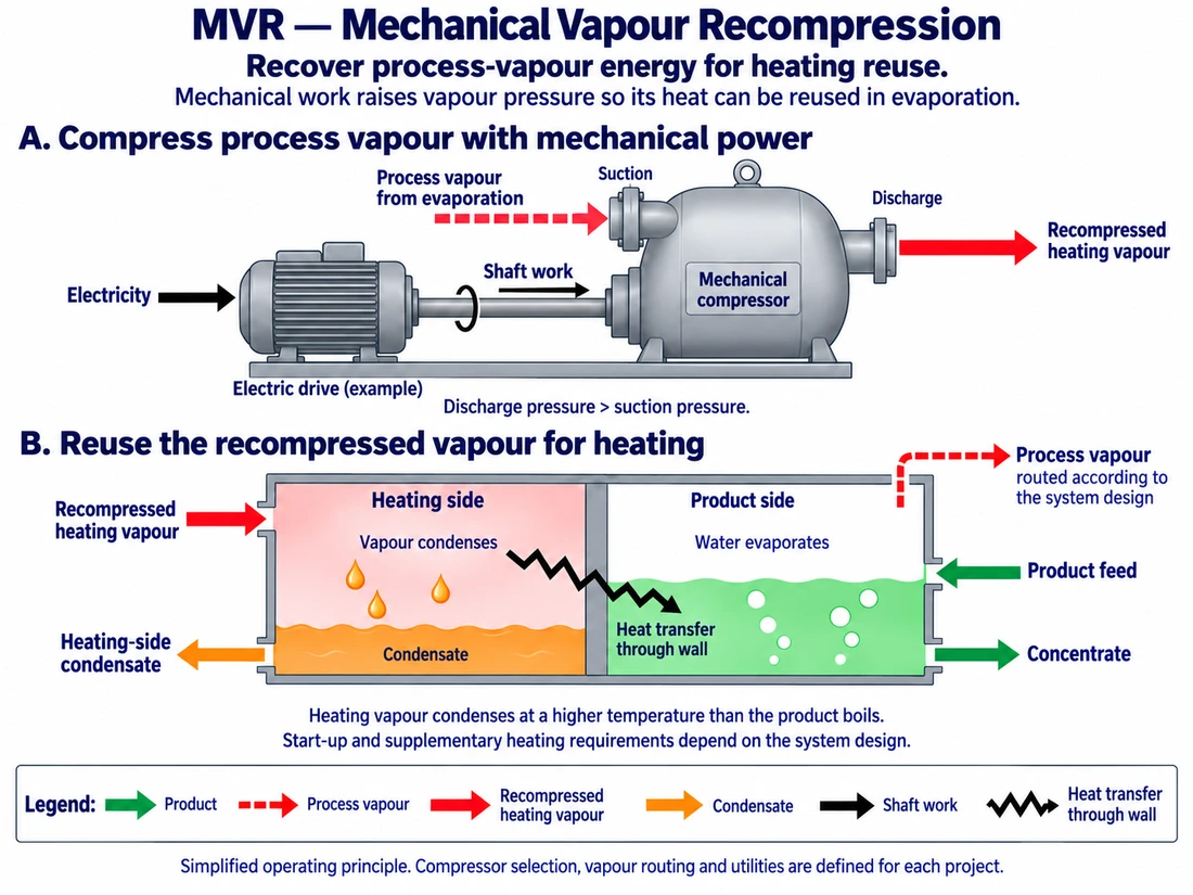
MVR uses mechanical power to raise the pressure of process vapour so it can supply heat to the evaporation system. The recompressed vapour condenses on the heating side and transfers heat through a separating wall to the product. Condensate leaves the heating circuit, while further water evaporates from the product. An electric drive is shown as an example of the mechanical power source. Compressor selection, vapour routing, and start-up or supplementary heating requirements are defined for each project.
Simplified operating principle. Compressor selection, vapour routing and utilities are defined for each project.
View full-size mvr operating principle
Tab to the image area and use the arrow keys to read the full diagram. Tab again to leave the area.
Selecting the Overall Configuration
MNM evaluates the finishing stage, number of effects and vapour-recompression arrangement as parts of one process design.
TVR or MVR can be considered alongside a multiple-effect arrangement where appropriate. Where a Finisher is required, falling film or forced circulation is selected according to the product’s viscosity, flow behaviour and final concentration duty.
The resulting configuration follows the product requirements, available utilities, operating conditions and project investment.
07 / Evaporation
Defining the Evaporation Duty
Three quantities establish the production basis: the feed entering the system, the water removed by evaporation and the concentrate leaving the system.
These are specified separately for the selected product and duty.
| Design input | What it establishes |
|---|---|
| Product and feed characteristics | The material and conditions the system must handle |
| Feed rate | The quantity entering per unit of time |
| Incoming and target concentration | The required change in concentration |
| Water-removal requirement | The evaporation duty |
| Concentrate output | The production rate after concentration |
| Viscosity at operating conditions | The basis for evaluating product flow, film formation and circulation |
| Product temperature constraints | Conditions relevant to thermal design |
| Product range | Differences between products processed in the system |
| Steam, electricity and cooling water | The basis for energy selection and utility requirements |
| Operating hours | The basis for evaluating operating requirements and investment |
| Upstream and downstream processes | Feed, discharge and control interfaces |
08 / Evaporation
Reference Application: Pineapple Juice
An existing MNM reference describes a triple-effect falling film long tube evaporator with the following feed basis:
| Parameter | Reference value |
|---|---|
| Product | Pineapple juice |
| Evaporator arrangement | Triple-effect falling film long tube |
| Feed rate | 8,000 L/h |
| Incoming concentration | 12 °Brix |
These values describe the reference feed conditions. The stated 8,000 L/h is the product feed rate, not the water-evaporation rate or concentrate output.
Other duties are designed around their own product and production requirements.
09 / Evaporation
Engineering, Project Delivery & Performance
MNM designs and manufactures the evaporator equipment in-house and specifies and procures the associated components.
Project services cover design, manufacture, procurement, installation, commissioning and after-sales support. Equipment, services and interfaces are defined in the agreed project scope.
Guarantees relating to the evaporator equipment, process performance and agreed product-quality targets are established in writing. The agreement defines the guaranteed values or targets, feed and operating conditions, test methods and acceptance criteria.
Discuss Your Evaporation Project
Contact Us
Address: 107/1 Moo 5, Wang Phong, Pran Buri, Prachuap Khiri Khan 77120, Thailand.
Tell us what you want to concentrate, the approximate production rate and the starting and target concentrations, where known.
For an existing line, include the upstream and downstream processes and the available steam, electricity and cooling water.
For a finishing application, describe the concentrate leaving the main evaporator, its viscosity at the relevant operating temperature where available, and the condition required by the next process.