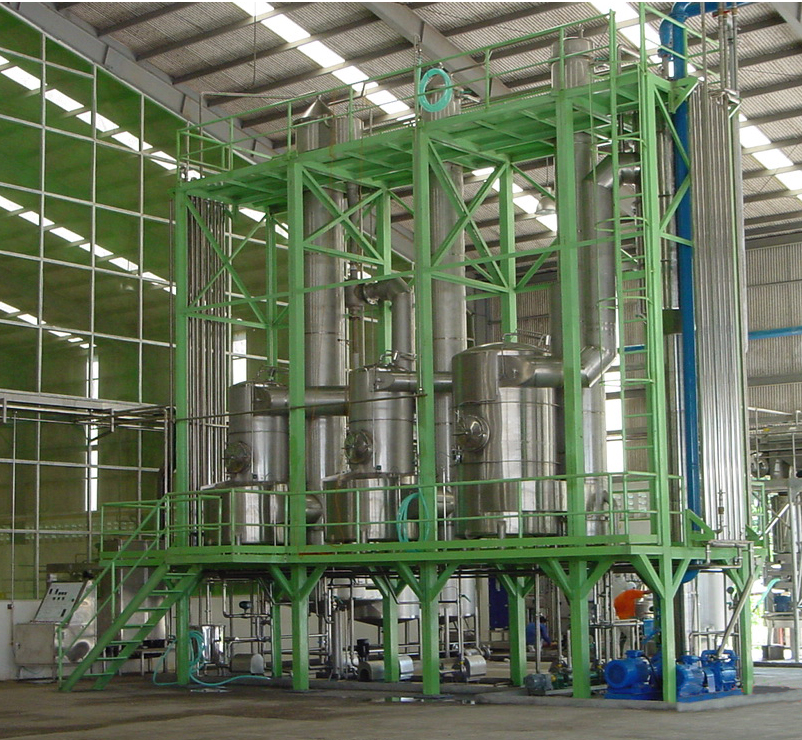
Evaporators

– Food processing
– Essential , Alcohol recovery
– Chemical processing
– Wastewater treatment
– Pharmaceutical
– Distillation
Introduction
• The objective for food processing : To create less water activity to assist in microbiological growth and assist in reducing transportation, and storage costs
• The objective for other processing : To remove water from the liquid product to obtain concentrated version
Concentration
Specified are designed in to “Total Soluble solid” (TSS) or “Brix” (Bx)
Power Source designed
It’s dry saturated Steam , Pressure require either Low or Medium (LS/MS) preferably
Steam Economic
• If the feed is near the boiling point at the pressure in the first effect, 1 kg of steam will affect the evaporation of almost 1 kg of water. The first effect operates at a temperature that is high enough for the evaporated water to serve as the heating medium for the second effect
• Again, here almost another kg of water is evaporated and this can be used as a heating medium for the third effect
• At a very rough approximate, for example almost 3 kg of water will be evaporated by using 1 kg of steam in a triple effects evaporator. However, if the effects are more than triple, this will increase the steam economy but it should not be more than quintuple effects as the steam saving is not worthwhile to invest the cost in.
Multiple effects :
• Single effect consumes steam equivalent to 1/1 with Evaporation rate
• Double effects consume steam equivalent to 1/2 with Evaporation rate
• Triple effects consume steam equivalent to 1/3 with Evaporation rate
• Quadruple effects consume steam equivalent to 1/4 with Evaporation rate
• Quintuple effects consume steam equivalent to 1/5 with Evaporation rate
Recompression :
Thermal Vapor Recompression (TVR) system save up to 1.2 to 1.75 times
Multiple effects are as the following design basis:
• Steam is used only in the first effect, then the vapor is reused as a heating medium in another evaporator chamber til to the last effect. Then the vapor flows to condensing stage and the partially concentrated product leaving the first effect is introduced as feed into the second effect, then to the last effect to obtain the final TSS or brix as requirement.
Flow pattern in a multiple effects Evaporator is as the following design basis:
A : Forward-Feed multiple-effects evaporator
• The fresh feed is added to the first effect and flow to the next in the same direction as the vapor flow
• This method of operation is used when the feed is hot or when the final concentrated product might be damaged at high temperature.
Figure 1 : Simplified diagram of a forward-feed triple effect evaporator

B : Backward Feed multi-effects evaporator
• The fresh feed enters the last and the coldest effect, and continues on until the concentrated product leaves the first effect
• This method of reverse feeding is advantageous when the feed is cold since a small amount of fresh cold , liquid must be heated into a higher temperature than the second and first effect.
• This method is also used when the concentrated product is of high viscosity, the high temperature in the early effect reduces the viscous and gives reasonable heat-transfer coefficients
Figure 2 : Simplified diagram of backward-feed triple effect evaporator

C : Parallel- Feed multi-effect evaporators
• This method involves the adding of fresh feeding and withdrawal of the concentrated product from each effect
• The vapor from each effects is still used to heat up the next effect, and this operation method is mainly used when the feed is almost saturated and solid crystals are the product- such as the evaporation of brine to make salt
Figure 3 : Simplified diagram of Parallel-feed triple effect evaporator

Design standards
• Vessel Pressure : Refer to ASME standard by PV Elite software
• Process installation material : Refer to ASME standard
• Piping installation : Refer to ASME & ANSI standard by CADWORX software
• Electrical & controlled design : Refer to IEC standard
Fabrication standard refer to : ASME section VIII Division 1
Materials
• All parts in contact with product are made of stainless steel, AISI 304
• All parts in contact with product and in heat exchanger are made of stainless steel, AISI 316
• Skid structure are made of Hot-dipped galvanized carbon steel.
• The majority of components, Instruments and Equipment are Worldwide Brands
Optional are available
• Insulation : Piping , Equipment and Vessel
• Automatic Operating : Controlling / Indicating / Data logging / Diagnostic & Fail-safe by HMI
For flow rate, pressure, level and temperature etc
For Operating Sequence mode as of specified in Operating principles
• Automatic concentration controller c/w Finisher evaporator
• Product cooler system
• Start plant mode is to build up the vacuum stage, start circulation cooling water at condenser first then start vacuum pump until vacuum pressure gain to 25” Hz
• Water filling mode is water fulfilled in the system stage, start the product feed pump to extract water from the Balance/Feed tank, and deliver to Pre-heater, When the water reaches to each effect, start their effect extraction pump then return water to Balance/feed tank then circulate
• Sterilization in place (SIP) mode in the case of ood processing only, start preheat/sterilization then step up the steam supply and control temperature at 90 degree C then circulating the full loop until reaches time limit of 25 minute
• Water production mode is the stage of simulating the water evaporation before production, start the first effect steam supply until the water evaporation rate reaches the production requirement and then, keep all conditions such as temperature, pressure, level and flow to wait for the production mode.
• Production mode when product is ready with all constancy kept such as initial concentration, temperature, solid content so it is recommended to have dual feed tank at least to feed to Evaporator as following stages
• Water purging by product
• Product return to feed/balance tank to build up concentration
• Product concentration reach to target
• Concentrated product feed out to next stage (Blending tank)
• Shut down & CIP mode is to stop the production and Clean In Place mode after stopping the production. When the product in feed tank is at falling level, the system shall be alarmed to operator’s acknowledgement or attention to act in the shutdown mode as the Evaporator cannot be stopped immediately, otherwise, the fouling will occur.
After an operator starts the shut-down mode, the system will be as following steps:
Purge product by water: close feed product valve, open water valve & drain valve then waiting for all product to be out from the system then return water to balance/feed tank and circulation.
Reduce vacuum pressure : open vacuum release valve until boiling temperature in the last effect goes up to 65ºC.
Dose CIP solution : Dose into balance/feed tank until concentration reach to 1.5-2% by volume of the water in the system.
Circulate CIP solution : Circulate for 30 minutes.
Purge CIP solution by water : All step is the same as product purge stage
Stop plant : step down all steam supply until the temperature in first effect is down to 40-45ºC then close vacuum pump, condenser pump, condensate pump and finally close all product pumps
A : Long tubes rising film Evaporator
• This type allows to boil inside 6-12 meter long vertical tubes
• The product film upward movement of vapor causes a thin liquid film to move rapidly upward
• A temperature differential of at least 14ºC between the product and the heating medium is necessary to obtain a well-developed film, high convective heat-transfer coefficients are achieved in the system
• Low capital cost.
• Medium capacity
Schematic flow chart

Photo / 3D overview


B : Long tube falling film Evaporator (The best quality)
• It has a product thin film moving downward under gravity on the inside of the vertical tubes
• This is more complicated system than rising film evaporator
• The residence time is about 20-30 seconds compared with a residence time of 3-4 minutes in a rising film evaporator
Both types of rising and falling film suit application to low viscosity liquid product and non-fouling sensitive product
Schematic flow chart

Photo / 3D overview


C : Long tubes forced circulation Evaporator
• Consists of non-contact heat exchanger where liquid is circulated at high rates
• A hydro-static head is used to eliminate the boiling of the liquid
• The temperature difference across the heating surface in the heat-exchanger is usually 3-5ºC
• Axial flow pumps are used to maintain high circulation rate with linear velocities of 2-6 m/s
• This method is low capital and operating costs when compared with other type of evaporator
This type suit application to Paste, High pulp and fouling sensitive product
Schematic flow chart

Photo / 3D overview


D : Scraper agitator film Evaporator
• Designed for High viscous product, crystallized product, high heat sensitive product
• Heat transfer coefficient and turbulence is increased by mechanical agitator of this liquid film
• High capital cost & High maintenance cost
• Low capacity


